Injection-locked oscillators, frequency dividers and multipliers
Divide-by-Odd-Number Injection-Locked Frequency Dividers
High-speed frequency dividers (a.k.a prescalers) are essential building blocks in wireless and wireline communications for functions such as frequency synthesis, quadrature signal generation, and multiplexing (MUX/DEMUX). For example, a prescaler is one of the major components in a phase-locked loop (PLL) (see Fig.1), which is widely used as frequency synthesizers in a radio transceiver. Currently, static or dynamic digital dividers are commonly used in RF/microwave PLLs [1]. They have simple structures, large bandwidth, and good robustness over process variations [2]. As the radio operation frequencies increase beyond the low GHz range, however, power consumption of digital dividers becomes a problem. It becomes increasingly difficult for them to meet a reasonable power budget. This is especially challenging in low-power mobile applications. Furthermore, due to large power dissipation, high-speed digital dividers can also introduce considerable noise degradation. Therefore, a frequency divider with better power efficiency is urgently needed.
![Fig.1 Prescalar in a typical charge-pump PLL [1].](https://www.hajim.rochester.edu/ece/sites/laics/wp-content/uploads/2022/11/pll.gif)
Injection locking is a special type of forced oscillation in nonlinear oscillators. Suppose a signal of frequency &omegai is injected into an oscillator, which has a self-oscillation (free-running) frequency &omega0. When &omegai is quite different from &omega0, “beats” of the two frequencies are observed. As &omegai approaches &omega0, the beat frequency (|&omegai-&omega0|) decreases. When &omegai enters some frequency range very close to &omega0, the beats suddenly disappear, and the oscillator starts to oscillate at &omegai instead of &omega0. Fig.2 shows this nonlinear behavior. The frequency range in which injection locking happens is called the locking range. Injection locking also happens when &omegai is close to the harmonic or subharmonic of &omega0, i.e., n&omega0 or 1/n&omega0. They are called harmonic (or superharmonic) and subharmonic injection locking, respectively.
A harmonic-injection-locked oscillator can be used as a frequency divider, namely, an Injection-Locked Frequency Divider (ILFD)[3,4,5,6]. An ILFD has inherent advantage in both speed and power dissipation compared to a digital divider. It is fundamentally an oscillator at the subharmonic frequency of the input signal, which effectively lowers the speed requirement for the process technology by n-fold. As a resonant circuit, only a fraction of the stored energy is dissipated in every cycle, which is determined by the quality factor Q of the resonator. This means that an ILFD can have significantly lower power consumption than a digital divider. The disadvantages of ILFDs are the limited locking range and division ratios. While the locking range enhancement technique is proposed in [4], This work of Divide-by-Odd ILFD is aiming at solving the problem of division ratios.
Divide-by-2 ILFD
As shown in Fig.3, a differential LC oscillator has become a popular choice for ILFDs[4]. When there is no input signal, i.e., the oscillator is free-running, there exists a signal at node A (the drain of the tail transistor, Mtail), which is at the second harmonic of the free-running oscillation frequency f0. Therefore, this topology is inherently suitable for divide-by-2 operation. On the other hand, it can only support frequency division ratio of even numbers (2, 4, 6 …) due to the differential nature. This would limit its usage in applications where odd-number division ratio (e.g., divide-by-3) is more desirable.

Such a differential LC ILFD can be viewed as a special regenerative divider[7] in which the M1, M2, and Mtail act as a single-balanced mixer, and the LC tank as the filter, with the feedback loop formed by the cross coupling (Fig.4). Frequency division happens when the 2nd-harmonic current is injected into node A by Mtail, and switched by the differential pair of M1 and M2 to generate the mixing products. Then all other harmonics except the fundamental frequency component are filtered out. Because the nonlinearity of the switching operation of the differential pair M1 and M2 has odd symmetry, it can only generate mixing products of odd-number orders, which corresponds to division ratios of even numbers (2, 4, 6 …). In order to support divide-by-odd-number operation, it is necessary to find a new topology for the built-in “mixer”.

Divide-by-Odd-Number ILFD
To address this problem and maintain the differential topology, we construct a differential cascode topology by adding another differential pair of M3 and M4 (Fig.5). M3 and M4 convert the differential injection signal Vinj into differential currents, which mixes with M1 and M2. Note M1 and M2 are no longer a differential pair because their source terminals are separated. Now the even-order nonlinearity of M1 (similarly M2) can generate the desired mixing product that corresponds to a division ratio of any odd number, e.g., 3.

A shunt-peaking inductor L0 can be inserted between the source terminal of M1 and M2 as shown in Fig.6. L0 resonates with the parasitic capacitances at the injection signal frequency ((2n+1)f0), and thus increases the signal amplitude injected into M3 and M4. It also provides a short-circuit current path at the fundamental frequency (f0). Therefore, the upper half circuit (M1, M2, L0 and resonator) works as a differential LC oscillator at the fundamental frequency. Overall, we confine signals at different harmonics locally by circuit topology and filtering.

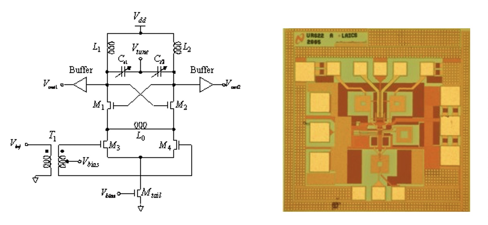
The differential input can be directly connected when the ILFD is integrated with an on-chip differential source like a differential VCO. When a single-ended source is used, a balun T1 is used to convert the single-ended input signal to differential signals (Fig.7). T1 also helps to match the input impedance of M3 and M4 to the source impedance.

A prototype divide-by-3 ILFD was designed using the new topology with input frequency from 16GHz to 18GHz (Fig.8)[8]. It uses an on-chip LC tank as the resonator. Note that other types of resonators can also be used in the implementations of the disclosed inventions. The prototype has been fabricated using a commercial 0.18um CMOS technology with low-resistivity epi silicon substrate and the die photo is shown in Fig.9 . The output signal spectrum in locked condition is shown in Fig.10. The 2nd and 3rd harmonics are -23dB and -21dB below the fundamental frequency, and a large part of them is contributed by the open-drain buffer at the output (single-ended measurement). The locking range increases from 0.3GHz at injection power of -14dBm to 1GHz at 4dBm with little change in the center frequency as shown in Fig.11. The corresponding input port voltage is calculated using S11 and shown in Fig.12. Note that this is the single-ended voltage (amplitude) at the primary of the balun with 1:1 transformation ratio. The ILFD can also be tuned by the varactors Ct1 and Ct2 with the free-running frequency from 5.37GHz to 6.1GHz and the extended working range for the ILFD is shown in Fig.13. Fig.14 shows the phase noise performance of the ILFD at different injection power levels. The phase noise of the free-running ILFD (no injection) and the signal source is also shown for comparison. Due to the low Q of inductors, the free-running phase noise is not good at all. When the ILFD is in locked condition, the phase noise follows that of the signal source with a 9-10dB reduction at large injection power (-3dBm and 3.7dBm) which matches well with the theoretical value 9.5dB. For small injection power (-8dBm), the phase noise degrades only at large offset frequency.
References
[1]B. Razavi, Monolithic Phase-Locked Loops and Clock Recovery Circuits,IEEE Press, 1996.
[2] B. Razavi, K.F. Lee, Ran-Hong Yan, “A 13.4-GHz CMOS Frequency Divider” Digest of Technical Papers IEEE Solid-State Circuits Conference, 16-18 Feb. 1994 Page(s):176 – 177
[3] R. Adler, “A Study of Locking Phenomena in Oscillators” Proc. IRE, vol.34, pp. 351-357, June 1946
[4]H. Rategh and T. H. Lee, “Superharmonic Injection-Locked Frequency Dividers,” IEEE J. Solid-State Circuits, vol. 34, pp 813-821, June, 1999.
[5]H. Wu and A. Hajimiri, “A 19GHz, 0.5mW, 0.35um CMOS Frequency Divider with Shunt-Peaking Locking-Range Enhancement,” IEEE ISSCC Dig. Tech. Papers, pp.412-413, Feb., 2001.
[6]B. Razavi, “A Study of Injection Locking and Pulling in Oscillators,” IEEE J. Solid-State Circuits, 39(9):1415-1424, Sept. 2004.
[7]S. Verma, H. R. Rategh and T. H. Lee, “A Unified Model for Injection-Locked Frequency Dividers,” IEEE J. Solid-State Circuits, vol. 38, pp1015-1027, June, 2003.
[8]H. Wu and L. Zhang, “A 16-to-18GHz 0.18um Epi-CMOS Divide-by-3 Injection-Locked Frequency Divider” Digest of Technical Papers IEEE Solid-State Circuits Conference, 5-9 Feb. 2006 Page(s):602 – 603