CYL Team
- Alan Tsien
- Stephanie Smith
- Thomas Chen
- Yuang Liu
Customer
Points of Contact: Chris Toomey, Clayton Summers, Dan Denison, and Scott Rudder
Faculty Advisors
- Mike Pomerantz
- Jessica DeGroote-Nelson
Abstract
There is a growing demand for non-spherical optics in industry. The manufacturing processes for cylinder lenses is different from that for spherical lenses. Instead of multi-axis polishing, polishing done only along the curved axis with the optic mounted in a drum. Thus, any misalignment of the polishing tool or mounting mechanism means that there will be axial twist to the bar. This is compounded when the bar is cut into individual lenses, where the internal stresses in the glass are suddenly released and the resulting lens is far out of spec.
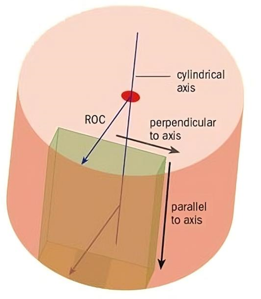
With existing metrology methods being either too imprecise or too expensive, this project is aimed at developing a tabletop metrology instrument capable of measuring micron-level and sub arc-minute errors in axial twist, wedge, and centration for plano cylinder lenses at a cost-effective price point. A non-contact optical measurement will ensure precision while provisioning for edge bevels and error analysis.
Potential Methods
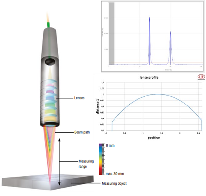
Chromatic Confocal Sensor: A method used widely in large-scale glass, these systems use white light and controlled-chromatic aberration, where monochromatic beams are focused at various distances away from the sensor. However, most do not have a large measuring range, or trade measuring range for a smaller spot size. Given the range of radii of the lenses, it would be difficult to quantify measurements.
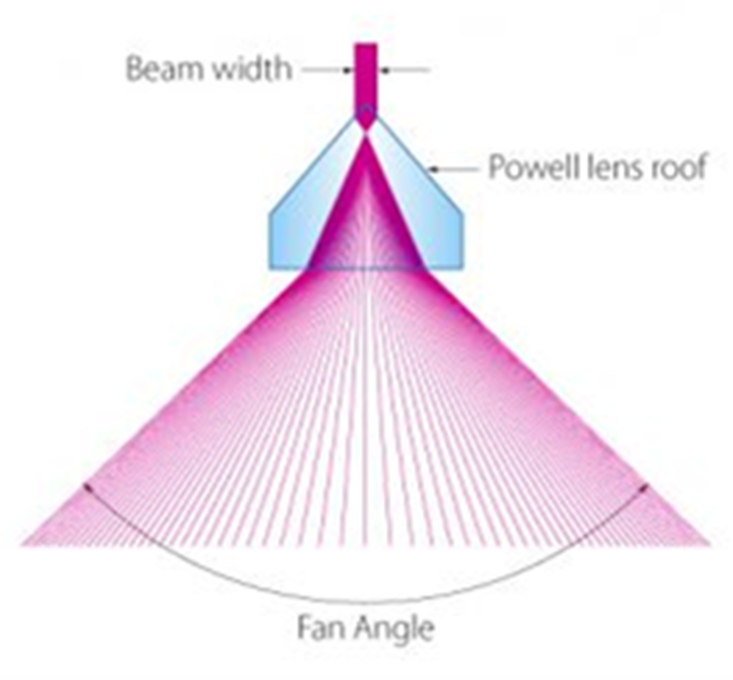
Scanning Interferometer with Powell Lens: A monochromatic Fizeau interferometer with a Powell lens as the collimating optic, this system creates a line with constant power across the plano cylinder lens under test. Using the laser line created by this lens would allow for fringes of constant brightness and increased visibility along the measurement. However, this method would require a motorized stage that would dramatically increase complexity.
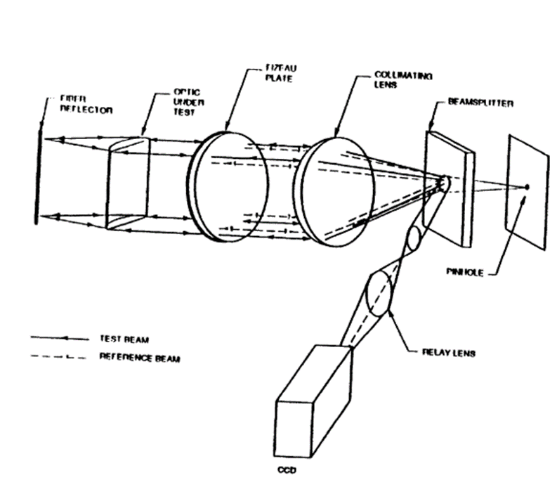
Fiber Optic Interferometer: A monochromatic Fizeau interferometer with a coated optical fiber as a reference cylindrical reflector for the lens, this system can display the interference fringes from the reflected fiber reference wavefront and the wavefront produced by the focusing cylindrical optic. However, the overall alignment process for the axes and datums must be carefully considered.
Interferometer Design
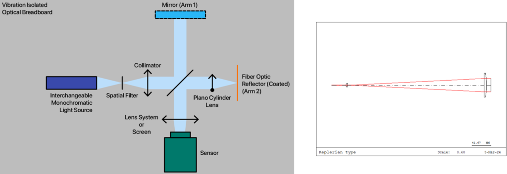
The Fiber Optic Interferometer method was the chosen focus for our design. Substituting the original Fizeau design for a Twyman-Green interferometer allowed for easier alignment with the additional arm and back-reflection from the mirror. Additionally, since a Fizeau plate will not be necessary and both beam paths from our beam splitter are being utilized, there is lower system complexity and greater light throughput. To characterize the performance of the entire test lens at once, a Keplerian beam expander was used, with a 5mm focal length ball lens as the first element due to its rotational symmetry, resulting in shorter overall length and less alignment complexity for the incident laser beam to fill the plano cylinder lens.
Testing and Alignment
In the initial stages of testing and alignment, our reservations regarding the 4% back refraction of the uncoated fiber were found to be justified. The reflected light from the fiber was too minimal to be useful for viewing fringes, and its intensity was the same as the reflections off uncoated surfaces of the plano cylinder test lens itself. This meant that the wavefronts from these surfaces would interfere with our returning cylindrical wavefront, making it impossible to characterize the lens itself.
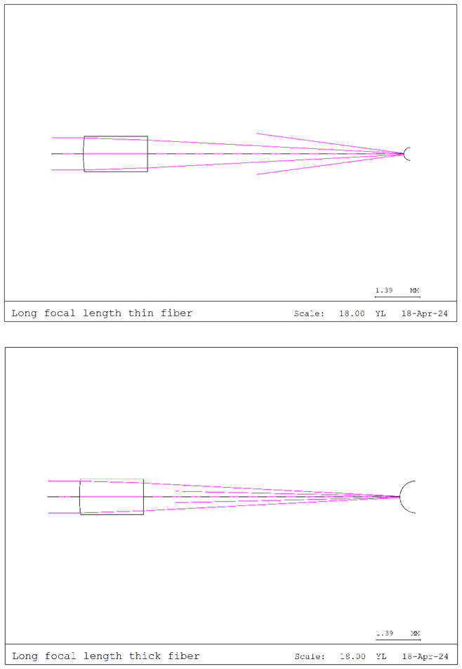
Our customers at OptoSigma connected us with Armadillo Sia and Molex, who provided us with a sample spool of aluminium and gold coated fiber, respectively. However, we found that while the intensity of the back reflection of the coated fiber is theoretically high enough to view fringes, the beam waist of the incident laser beam is too large to fully reflect off the diameter of the fiber optic. Viewing the equation ![]() , it can be seen that the two ways to decrease the beam waist are to decrease focal length of the plano cylinder test lens and increase the diameter of the reflective surface beyond that of an optical fiber.
, it can be seen that the two ways to decrease the beam waist are to decrease focal length of the plano cylinder test lens and increase the diameter of the reflective surface beyond that of an optical fiber.
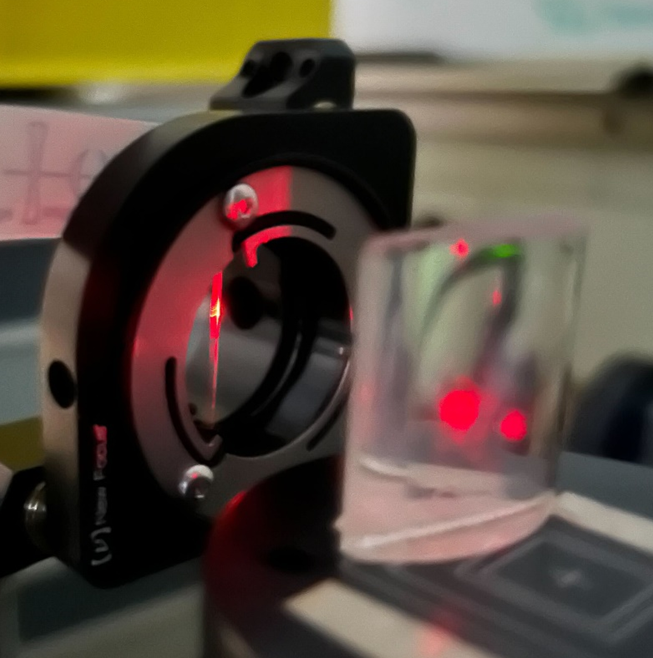
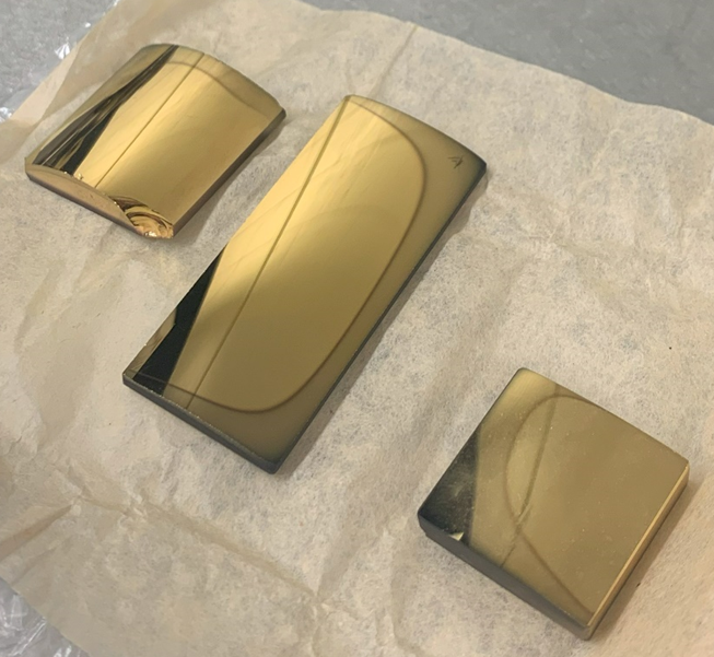
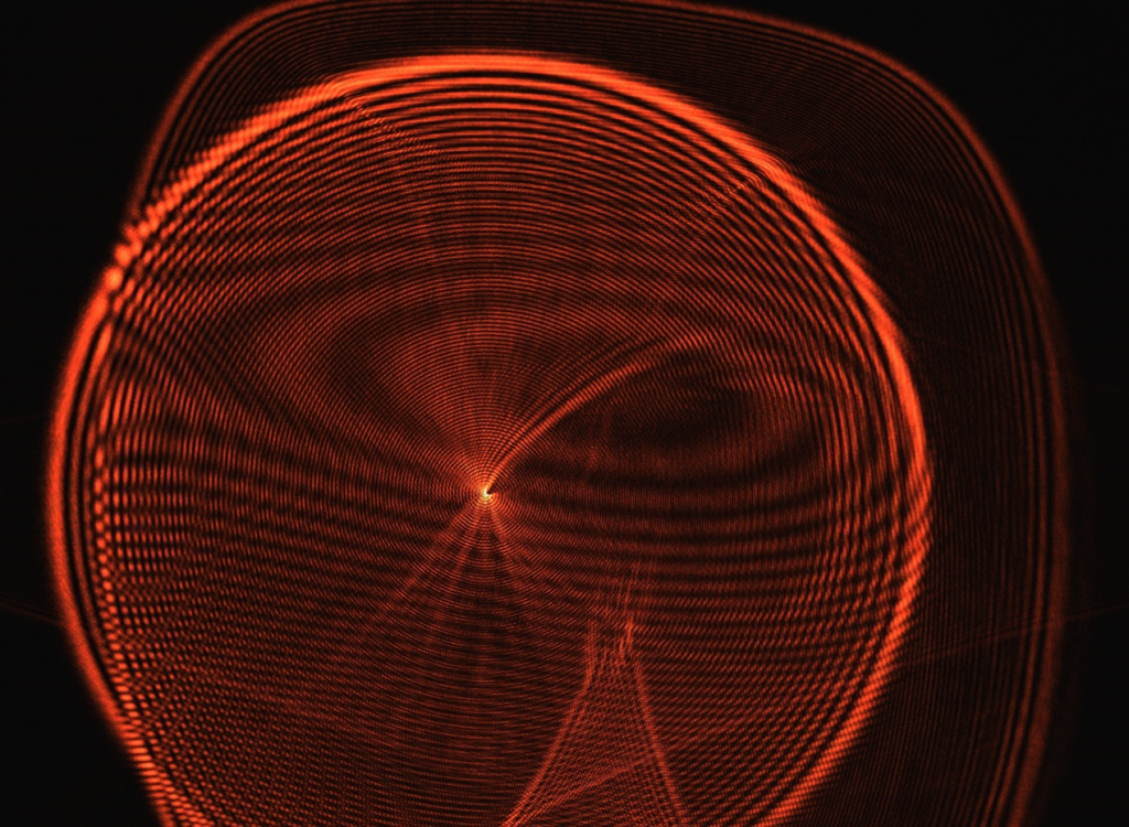
As the system will be used to test plano cylinder lenses of various focal lengths and sizes, the only option to decrease the beam waist is to replace the coated fiber with a larger reflective cylindrical surface. In the UR Nano lab, we used a Denton Vacuum sputter coater to deposit a 100nm gold film on a few spare plano cylinder lenses. Upon final testing with one of the coated plano cylinder lens, interference fringes were observed.
Results and Analysis
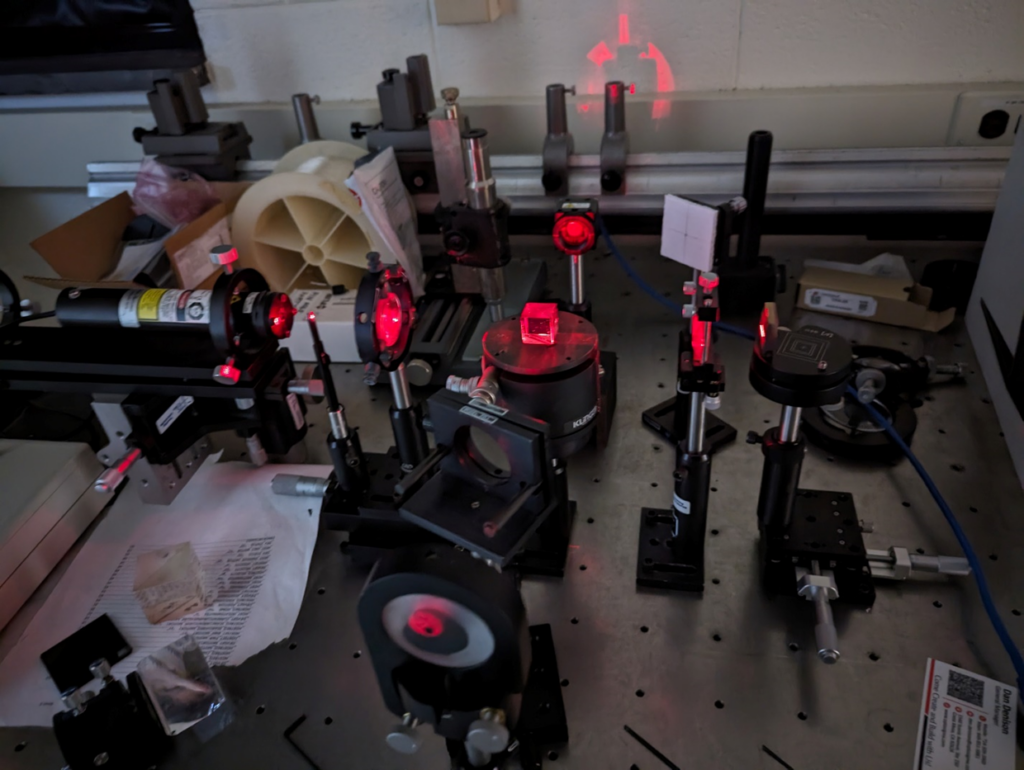
The final iteration of the system consists of a 0.5mW HeNe laser source, a Keplerian beam expander, a 50/50 non-polarizing beamsplitter, and a color CMOS sensor, all in a Twyman-Green configuration. The reference arm consists of a mirror and an optional ND filter, and the test arm consists of the plano cylinder lens under test and the gold coated cylinder lens.
The reference cylindrical reflector must be sufficiently large to account for the beam waist differences between the focal lengths of the test lenses. The surface of the reference must be of free of scratches and accurately characterized to reflect a known cylindrical wavefront. A CGH should be used to characterize the reference reflector. For all subsequent tests, since the single reference can accommodate a variety of focal lengths and does not need to be exchanged for different test lenses, the fringes of non-uniformity can be easily subtracted from the resulting measurement data. The light throughput between the two arms of the interferometer may also need to be balanced with an ND filter for maximum fringe visibility.
Conclusions
As expected, the alignment and setup of the interferometer are critical to our ability to have interference. A coated lens would likely be preferable over a fiber optic due to its greater size and datums for measuring relative alignment between the lens and reflector. For any future system design, we suggest creating a set of reference cylindrical surfaces that work with specific ranges of test lens focal lengths. Leveraging OptoSigma components, the system is currently suitable for low-volume testing and could be scalable for production use.
Acknowledgments and References
Customer: OptoSigma Corporation
Chris Toomey, Clayton Summers, Dan Denison, and Scott Rudder
Faculty Advisors: Mike Pomerantz and Jessica DeGroote-Nelson
Special Thanks: Wayne Knox, Greg Madejski, and Ed Herger
References:
“Cylindrical lenses offer many focusing options” SPIE Ltd, (2008, December 12). https://optics.org/article/37057
“Displacement Position Sensors: Confocal Sensor.” Micro-Epsilon, 2023. https://www.micro-epsilon.com/displacement-position-sensors/confocal-sensor//
“Powell Lenses,” In Stock Optics, 2023. <https://instockoptics.com/powell-lenses>.
“Powell Lenses,” Shanghai Optics, 2 February 2022. https://www.shanghai-optics.com/powell-lenses/.
Joseph M. Geary, “Overview of cylindrical optics testing using a fiber optic reference,” Proc. SPIE 2536, Optical Manufacturing and Testing, (8 September 1995); doi: 10.1117/12.218461.
“SPIE Optics and Photonics 2024.” Conferences and Exhibitions, SPIE, <spie.org/conferences-and-exhibitions/optics-and-photonics>.