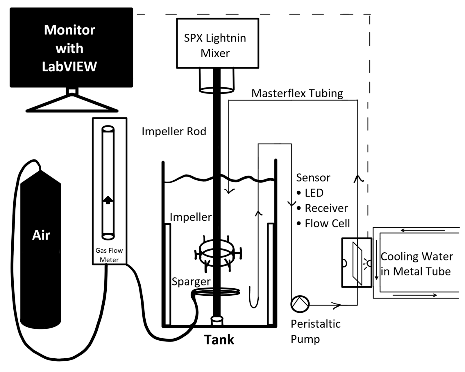
Experimental Set Up
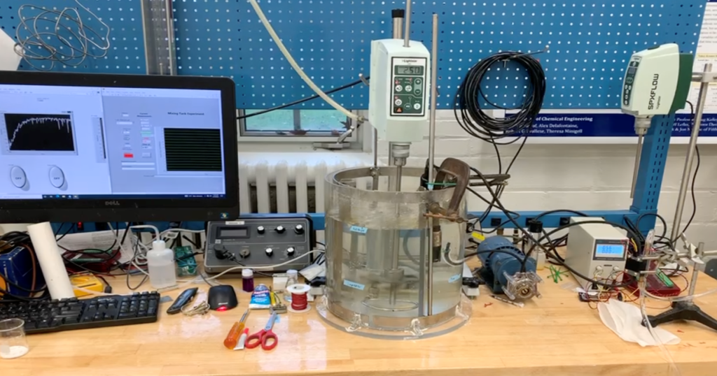
The above figure shows the experimental set up that Team Chocolate used. In the center, there was a Lightnin Mixer and 4-baffled tank with gas sparger supplied by SPX FLOW. The left of the image shows the O2 probe set up with LabVIEW on the computer monitor to collect sensor data. The right shows the pump, power supply, and UVC LED sensor designed by Team Chocolate. In a standard trial, the RPM = 250, pump flow rate = 5.12 mL/s, air flow rate = 0.082 SCFM, and power supply = 5.6-5.7 V.
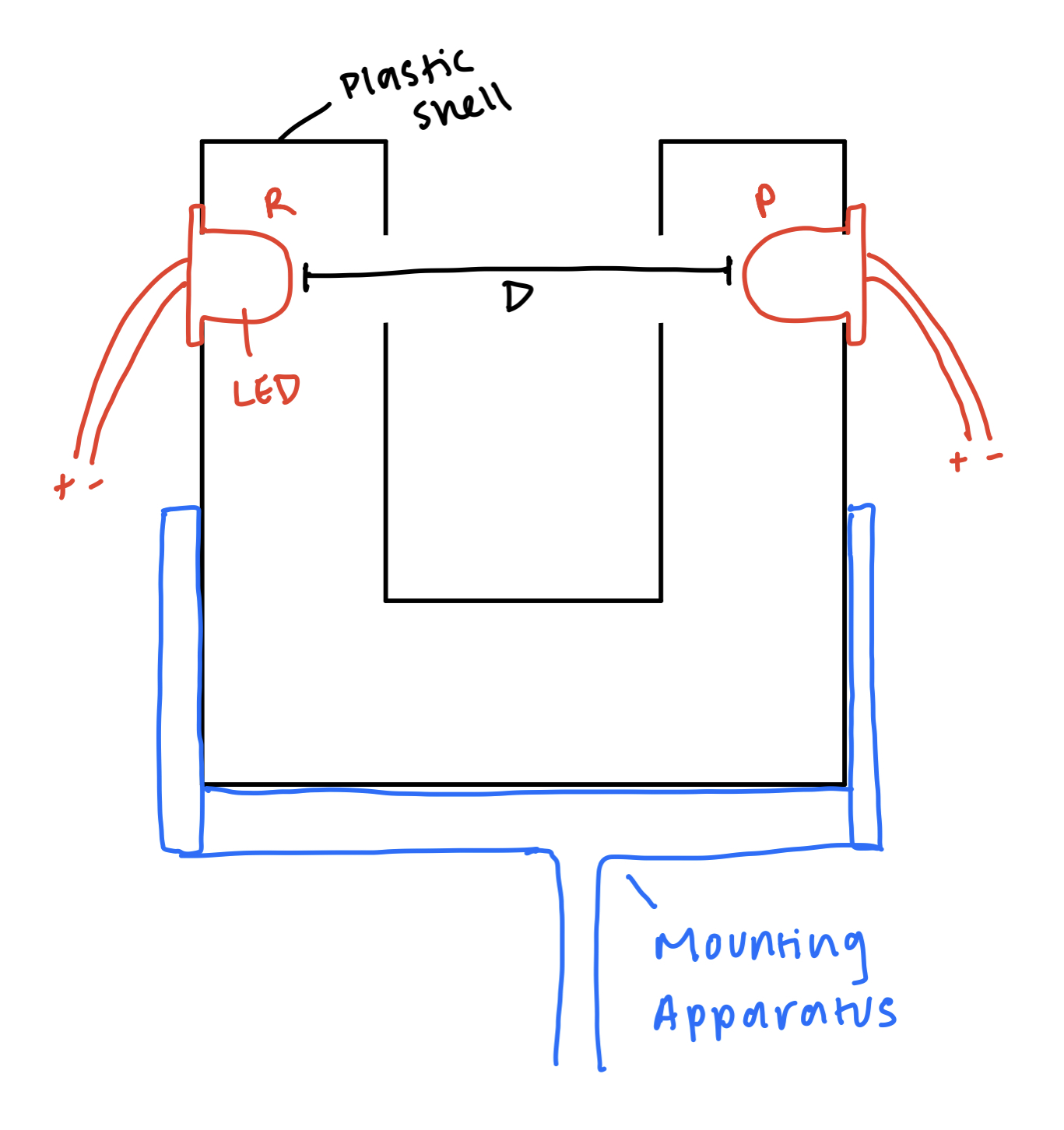
The sensor’s design started out in a C-shape that would be mounted in the tank to give continuous readings. One side would house the LED and the receiver would be mounted on the other end. This shape would allow reaction fluid to flow between the LED’s light path to the receiver.
The final design of the sulfite sensor was influenced by several factors:
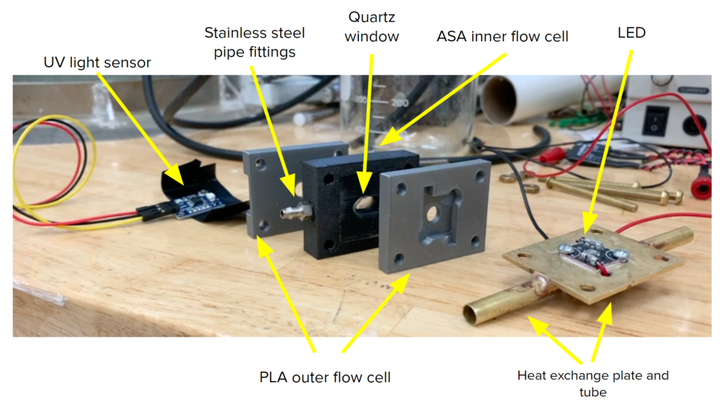
- The sensor utilizes UVC LEDs with a wavelength of 265nm and 275nm. This light source is harmful to the eyes and skin when directly exposed. This necessitates that the sensor be completely closed in a black box to avoid exposure.
- Because of the black box constraint, it was determined that the sensor should be mounted externally, and the reaction fluid would be pumped through the flow cell using a peristaltic pump.
- The final factor was the heat transfer of the LED, which when on generates 4.2 watts of power. In order to dissipate the heat generated the sensor was mounted to a cooling system that will keep the LED at an optimal operating temperature below 50 ℃.
The 3D models of the final sensor design below were graciously provided by Professor Kelley:
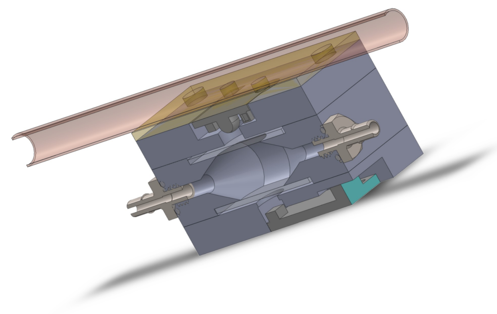
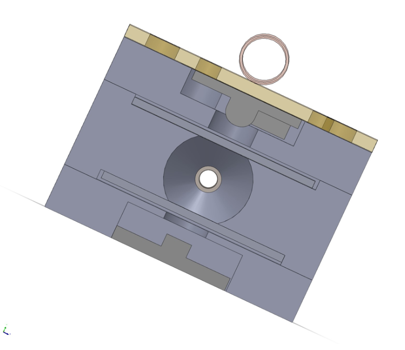
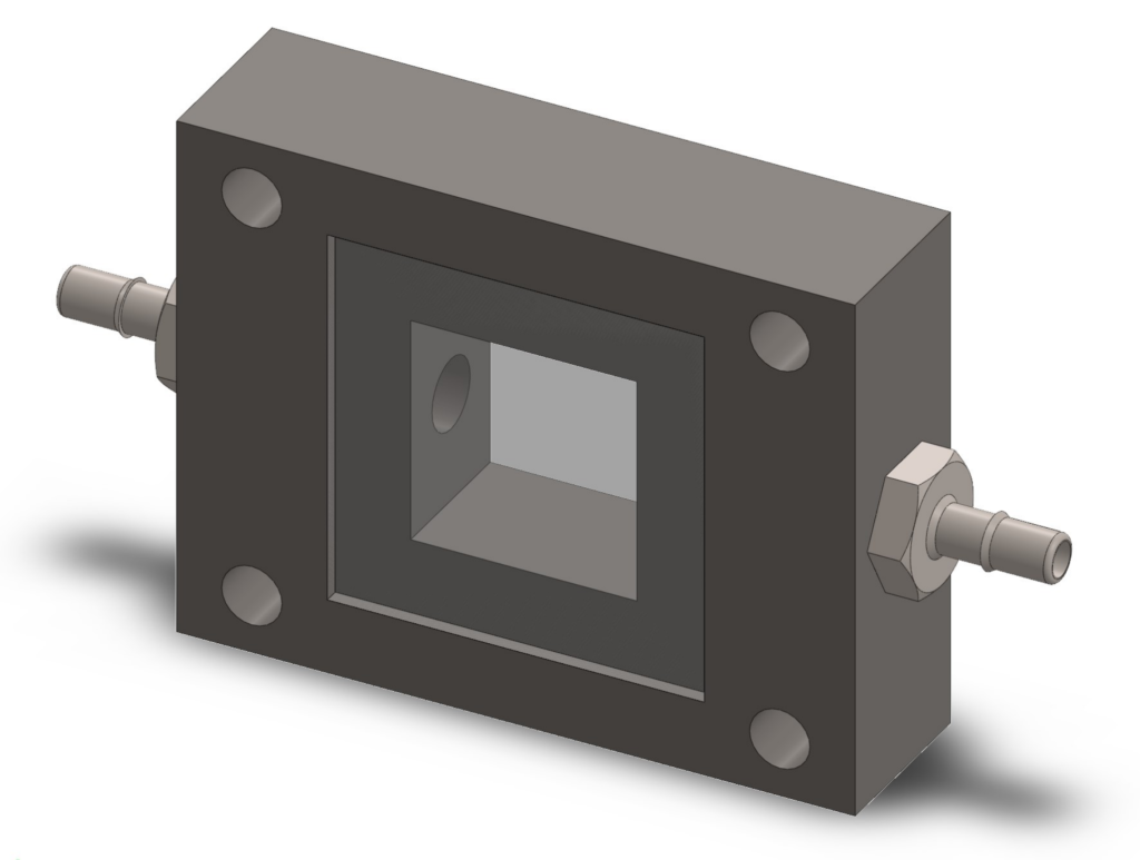
The final design had quartz microscope slides adhered to the flow cell body with RTV. The metal fittings also were sealed along the threads with RTV. In order to prevent the cell from leaking, it was printed with ASA and was painted with acetone to slightly dissolve the cell body.
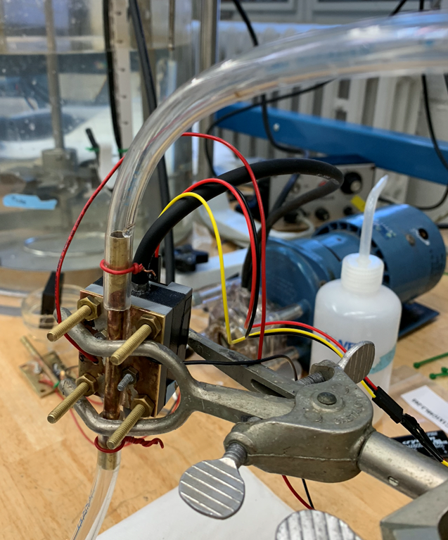
The sensor was then mounted vertially to prevent air bubbles from getting trapped. It was hooked up to the pump with reaction fluid and the chiller. The LED was connected to the power supply and the receiver was connected to the LabJack.
The figure below show the final P&ID for this system: