Team Members
- Jake Gonzales
- Evelyn Machado
- Otsile Rantshabeng
- Noah Rubin
Mentors
Sponsor
Calvin Uzelmeier
Project Manager
Christopher Muir
Abstract
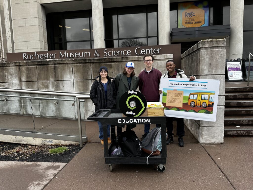
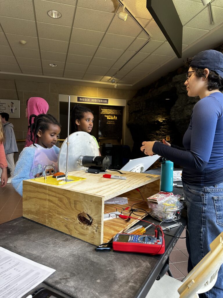
We were asked by the Rochester Museum and Science Center (RMSC) to create an exhibit for their How Things Works collection. We chose to create a display teaching about regenerative braking in electric and hybrid vehicles. To do so we manufactured a pulley and flywheel system attached to a generator. We also fabricated a storage system utilizing a lead screw to represent energy storage. In addition, a circuit was created to allow a user to operate the exhibit by turning the braking on and off as well as the utilization of stored energy. We then tested our exhibit at RMSC and observed user interaction with it to iterate on our design.
Problem Statement
With the advancement of technology in all STEM areas within the last 10 years, museums & science centers around the state of New York lack updated features/exhibits on these ideas. It’s important to educate kids in all fields of STEM and museums/science centers allow a great purpose of preserving, interpreting, and providing a space to acquire knowledge of our society that is outside of school. The Rochester Museum and Science Center has asked for the help of fellow Univ. of Rochester Mechanical Engineers to update their exhibition titled, How Things Work, to represent technology/conceptions that are important today. Designing a regenerative braking exhibit assists in educating guests on how everyday objects work, learning basic STEM concepts, and improving the skills of those who have trouble trying to overcome the rapid technological environment we live in now.
Requirements
- It must be designed for families with kids ages 5-15.
- Must feature a write-up and instructions.
- The exhibit must be conceptually distinct from or improve upon past exhibits.
- It has to be tested with multiple audiences.
- It must work when used improperly.
- It must meet ADA requirements.
- It has to be safe for unfacilitated use.
Specifications
- The exhibit must be within a 40 in x 60 in space envelope.
- The height of the exhibit can not exceed 6 feet.
- The forward reach must not exceed 20 inches.
- The wheel space underneath must exceed 20 inches.
- The maximum upward reach must not exceed 44 inches.
- The operation of the display must not require more than 5 pounds of force.
- There has to be a minimum allowable clearance underneath.
Design Selection
The team came up with three ideas of technological concepts that we could use for this project. One of the major considerations was modern relevance. The exhibit that our display is going in, How Things Work, has not been updated for over a decade so, choosing a topic that would have ongoing relevance was critical to update the exhibit to reflect more modern technology.
| Criteria | Definition | Pulleys | Regenerative Braking | Bike Gears |
|---|---|---|---|---|
| Simplicity | How complex is the design? | 0 | 2 | 0 |
| Modern Relevance | Do they see it in their everyday life? | 0 | 2 | 1 |
| User Interest | Is it interesting? | 0 | 1 | 1 |
| Experience Level | How knowledgeable is the team on this topic? | 2 | 1 | 2 |
| Cost | Is it within our budget? | 1 | 1 | 1 |
| TOTAL | - | 3 | 7 | 5 |
Assembly Components
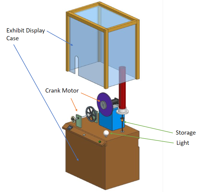
Manufacturing
Below are the sub-assemblies that make up our exhibit.
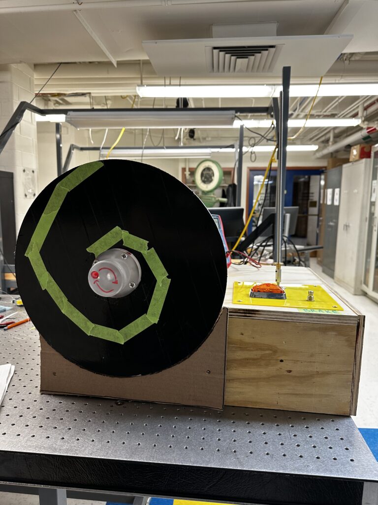
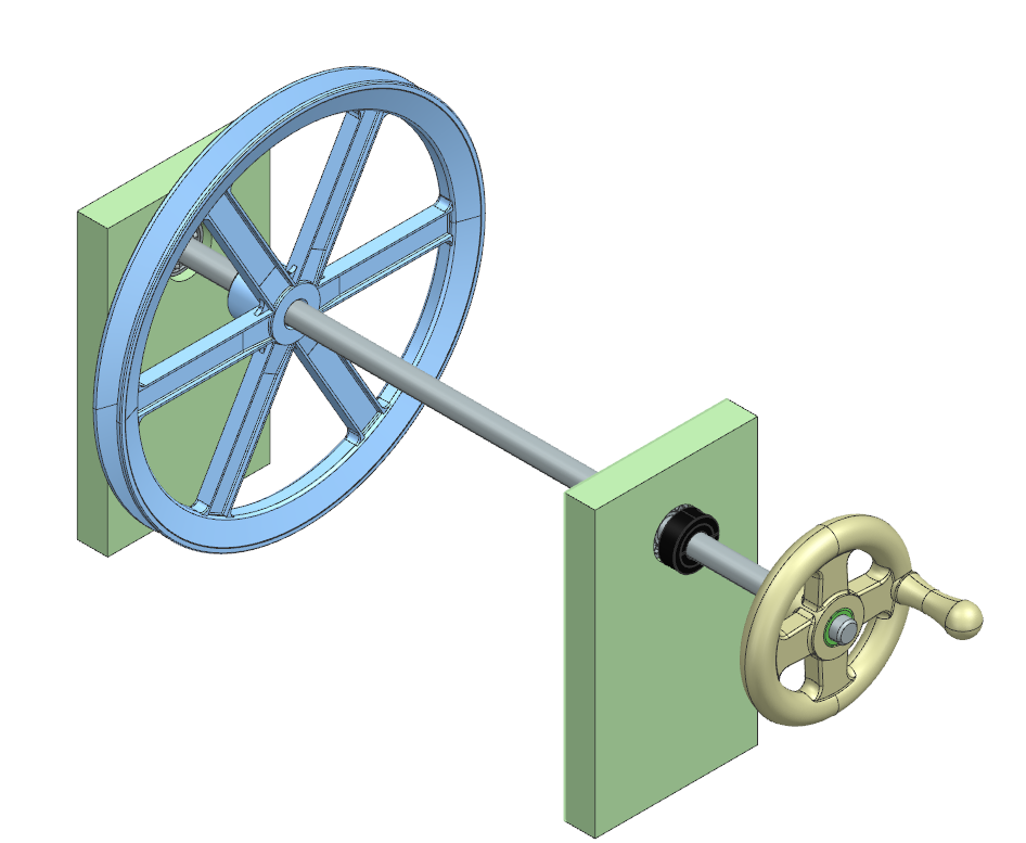
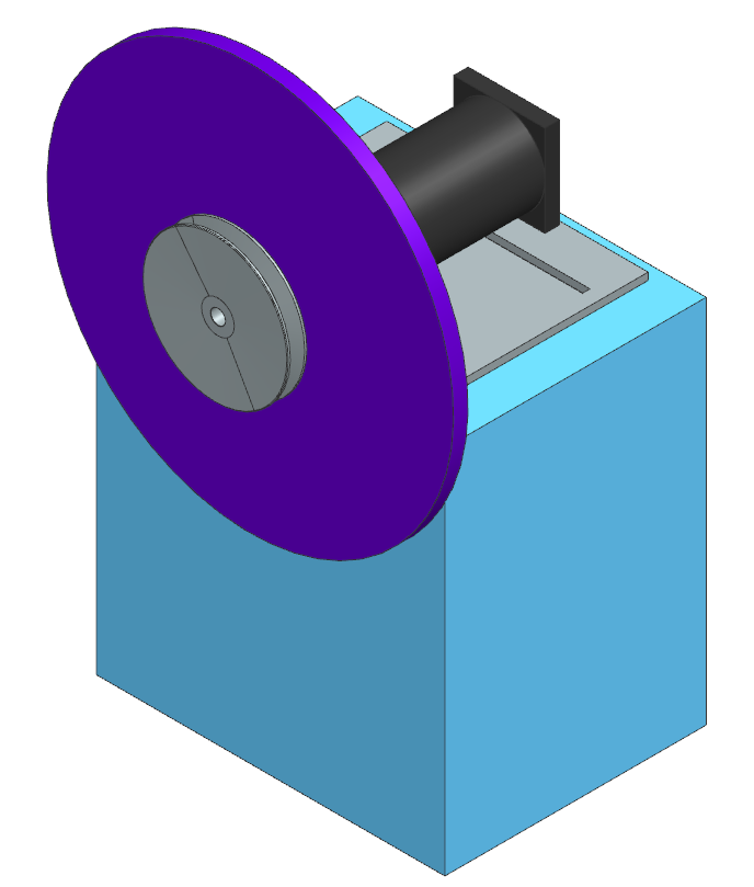
Motor-Crank
The crank subsystem contains a box to mount the motor, a flywheel, a motor shaft adapter, a v-belt pulley system, a mount for the crank shaft, and hand wheel. The box is constructed from ¾ in plywood, with two milled channels on the top board to allow for adjustable tensioning of the pulley. Wood used by the team was cut on either a table saw or bandsaw and is connected using either nails and wood glue or nuts and bolts. A piece of hot rolled steel sheet metal is bolted to the top and has the same milled channels, reducing the damage done to the wood by the mounting of the motor.
Motor Mount
For the motor mount we fabricated a box with with a metal plate affixed to the top. We then cut two parallel slots in the tops that the motor could be bolted through. The slot allowed for the motor to slide from side to side to make tensioning the v-belt much easier.
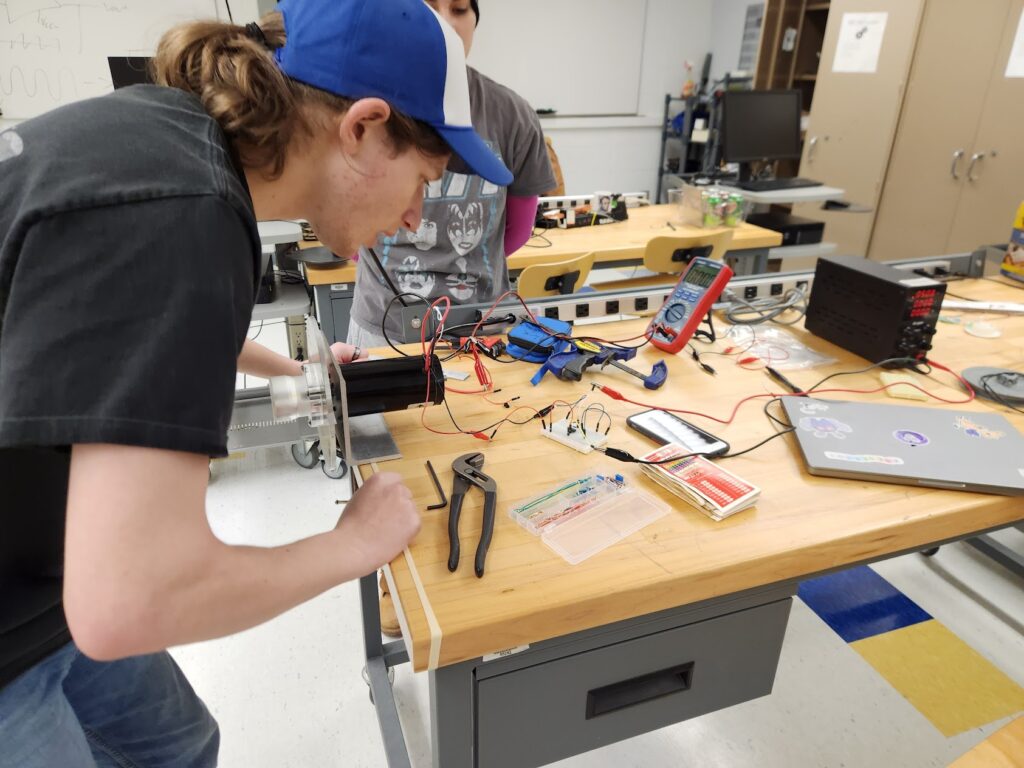
Circuit
The circuit consisted of a generator motor wired to a double-pole single-throw (DPST) switch leading to both a 0.13 F capacitor and the storage subsystem. The current draw of the storage subsystem generated a counter-torque in the generator causing the flywheel to slow down. This also charges the capacitor to about 9-10 V. A momentary switch button can then be pushed to cause the capacitor to discharge through a LED. A diode was also included to prevent the capacitor from back-driving the generator.
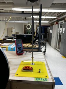
Storage
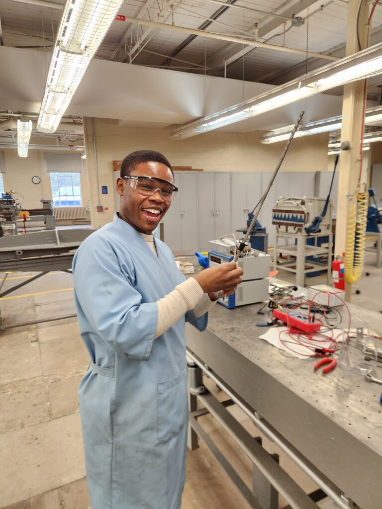
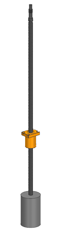
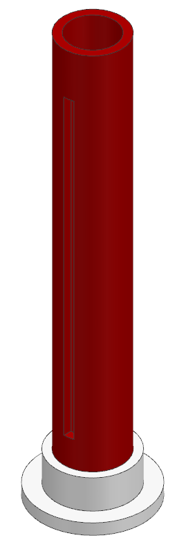
The storage subsystem consists of a steel non-self-locking lead screw, a plastic flange nut, a motor, a 3D printed key lock, a battery visual cylindrical casing made of PVC, and washers that assisted with driving the flange nut back down. The lead screw was attached to the motor vertically using a coupler that was manufactured using a lathe. Oil was applied to the lead screw to help reduce friction with the flange nut. The PVC casing was cut to a 19 in length using a saw blade, and the 0.375 in slit for the key lock was cut using a mill. The PVC casing was attached to the exhibit board using a PVC pipe flange. PLC was used for the 3D printed key lock, with 50% infill. A visual representation of a red, orange and green battery gradient was printed, and pasted on the outside of the PVC casing for easier visual representation.
Display Case
The display case was built by the very helpful Bill Mildenberger. The case consists of a 36 x 25 x 30 inch base with no bottom, an opening on the back of the base, 5 inches from the top to provide a space for our electrical components. The encasement is plywood bonded and acrylic is slotted into the plywood via dados, 5 sides to provide a clear 360 view of the exhibit. There is a slot in the acrylic that is made to be able to assemble the crank for the exhibit. We used 1/8 inch acrylic sheets and 3/4 inch pine sheathing plywood.
Prototyping
The first iteration was taken for testing at RMSC on 04/06/24. We wrote down observations/improvements discussed by users to polish the next iteration of our prototype.
Below are the finalized models of the sub-assemblies for our exhibit
-
CAD model of motor mount -
CAD model of lead screw mechanism -
CAD model of battery visual for storage mechanism -
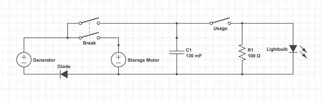
Finalized circuit diagram for our exhibit
Social & Environmental Impacts
By providing updated exhibits that reflect current innovations, the museum effectively engages visitors, especially children, in hands-on learning experiences. This fosters curiosity, critical thinking, and problem-solving skills which are all essential for success in today’s technology-driven world. The project also promotes awareness and encourages visitors to actively participate in shaping a future focused on eco-friendly and sustainable systems.
To minimize environmental impacts, the project harnesses kinetic energy from users to operate, reducing reliance on external power sources. Additionally, recyclable material such as wood is used, reducing waste generation, especially during iterations. From an ethical standpoint, ensuring accessibility and inclusivity in the exhibit design is paramount. The project prioritizes accommodating individuals with diverse backgrounds, abilities, and learning styles to ensure equitable access to educational resources.
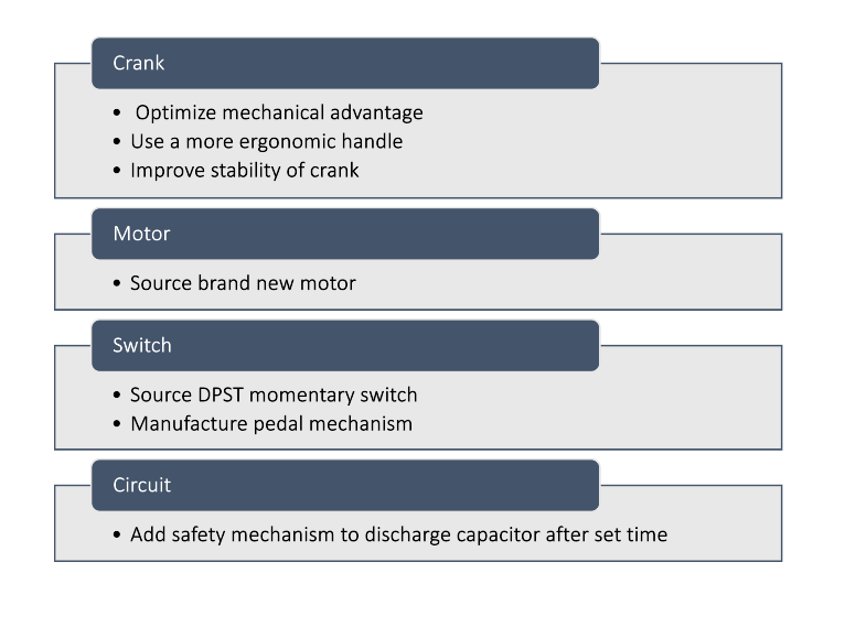
Future Works
Since we have merely made a prototype there are many ways in which the exhibit can be improved on. These would be our recommendations for future revisions.
Check out our presentation!