Orthopedic Rehab Senior design team

Matthew Wiele, Nathan Fricano, Rachelle Gomez-Guevara, Erin Nguyen, Cole Senecal
(From left to right)
Abstract
The objective of the project was to create a therapeutic device to assist patients with spasticity regain motion in their hands. The device is intended to be used during rehabilitation sessions for URMC Occupational Therapy. This project is a continuation from last year. The design process began by remaking last year’s device and taking it into the URMC clinic to test on real patients. After several iterations of new design ideas, the final design transitioned from motor-operated to human-operated. By making the device human-operated, there is less chance of pain or injury to the patient since they are controlling the amount of force being exerted by the device. Siemens NX was used to create CAD for all the design parts and then 3D printed to prototype. The final prototype was tested on the team members and then brought into URMC to test on patients. Some requirements were met while others did not completely pass, leaving room for future work to be done on this design.
Problem Definition
Patients that experience a stroke frequently develop spasticity in their hands, causing them to be unable to open or close their hands without assistance. Currently, there are no therapeutic devices that assist patients with spasticity to both open and close their hands while rebuilding neurological connections. The goal of this project is to create a therapeutic device that can assist both of those movements and can accommodate a wide variety of patients. This problem is important both to individuals who are undergoing hand therapy and those assisting with it, as the current solution requires hands-on assistance from a professional. This device is needed because it will provide a more effective treatment and will allow for greater freedom to the individual undergoing therapy. Overall, the device is designed to offer a greater quality of life to individuals with spasticity. For physical/occupational therapists, the device will provide more assistance during sessions and will prove to be an effective in-office and out-office tool for many of their patients. This device addresses the overreaching problem of limited rehabilitation technology accessible to patients by creating a new therapeutic device that will expand the current options available to individuals with spasticity.
T.H.O.R.
Therapeutic Hand for Occupational Rehab
Table I: Deliverables for T.H.O.R.
| Deliverables: | |
| 1: | Prototype therapeutic device |
| 2: | Theory of operation manual |
| 3: | Written report including test data and analysis |
| 4: | Optional interactive software |
Table II: Requirements for T.H.O.R.
| Requirements: | |
| 1: | Measure the range of motion of the fingers |
| 2: | Fit an adult hand |
| 3: | Aid an individual or multiple fingers in extension and flexion |
| 4: | Exert an adjustable force to aid in extension and flexion |
| 5: | Prevent the hyperextension of finger joints |
| 6: | Be portable |
| 7: | Aid in the abduction and adduction of the fingers |
Table III: Specifications for T.H.O.R.
| # Value | Units | Description | Method of Evaluation |
| ~ | Deg. | Range of Motion (ROM) in extension, flexion, abduction, adduction. | Goniometer |
| <1.5 | lbf | Overall weight of one and a half pound or less on the hand and wrist as determined by customer. | Scale |
| 1 | hrs | Device must run continuously. | Stop watch |
| 5 | lbf | Apply a force to the tip of the fingers to aid in flexion and extension of fingers. | Fish scale |
| 3 | lbf | Apply a force to aid in adduction and abduction of fingers. | Fish scale |
Design Iterations:
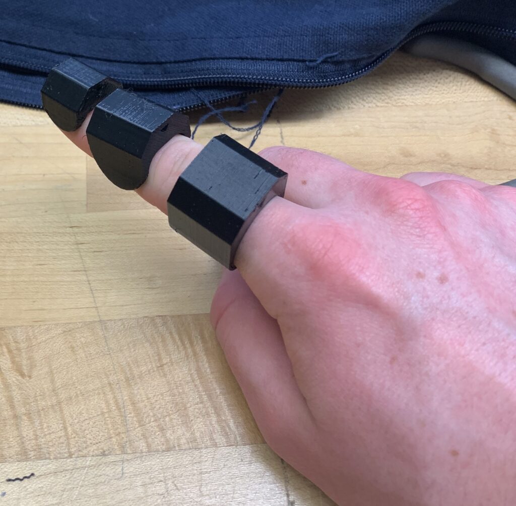
Concept from the 2023 URMC Rehab Team:
The original concept from the 2023 URMC Rehab Team consisted of a wrist cover, back of hand plate, and connected 3D printed sections on each joint of the finger. The original design is too rigid, does not allow the patient to use their complete ROM, only fits a few individuals, and is unable to produce enough torque to produce the necessary flexion and extension of the fingers. Fishing wire ran through the joints and back up the arm and was attached to a motor. This motor controlled the motion of the joints, but it was an ineffective way to apply force to the fingers.
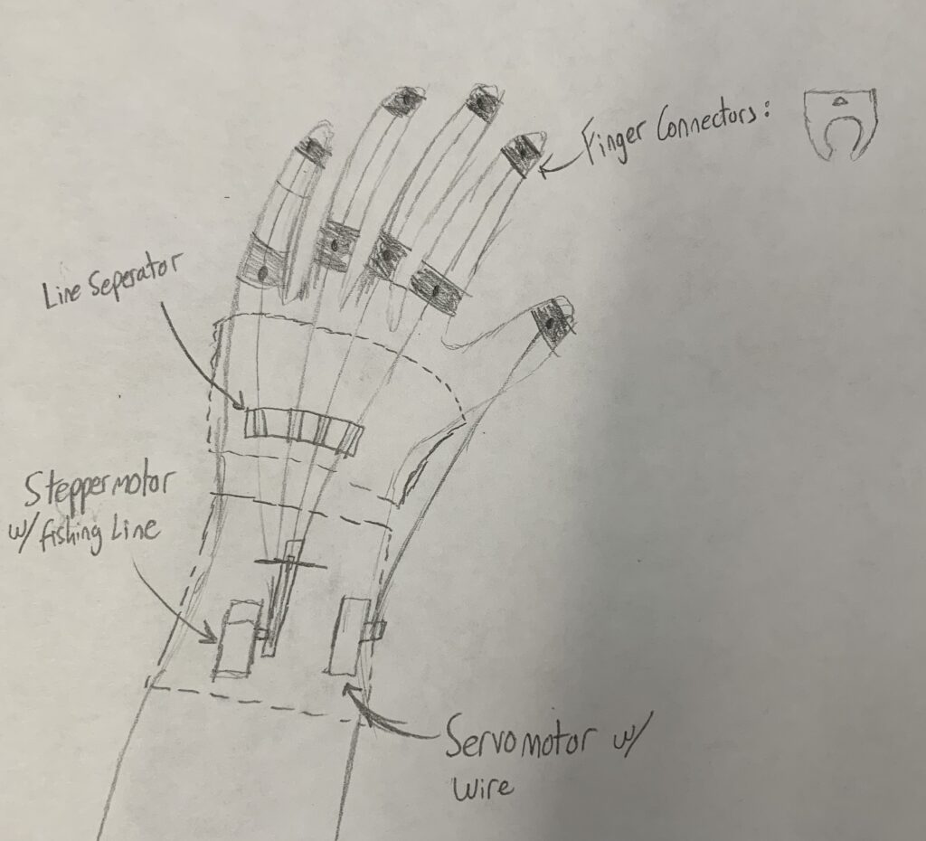
Design Concept I:
This design aims to remove said interference as well as improve adjustability of the links on the hand. This design would be made from a flexible rubber-like material to increase the number of patients it can fit and have a more comfortable fit on the hand in general.
Design Concept II:
To address the previously mentioned issues a bioinspired device would be the most ideal. This device would have insertion points at multiple locations resembling those seen in the human hand and would have silicon bases at the insertion points to provide cushioning and provide more sizing options.
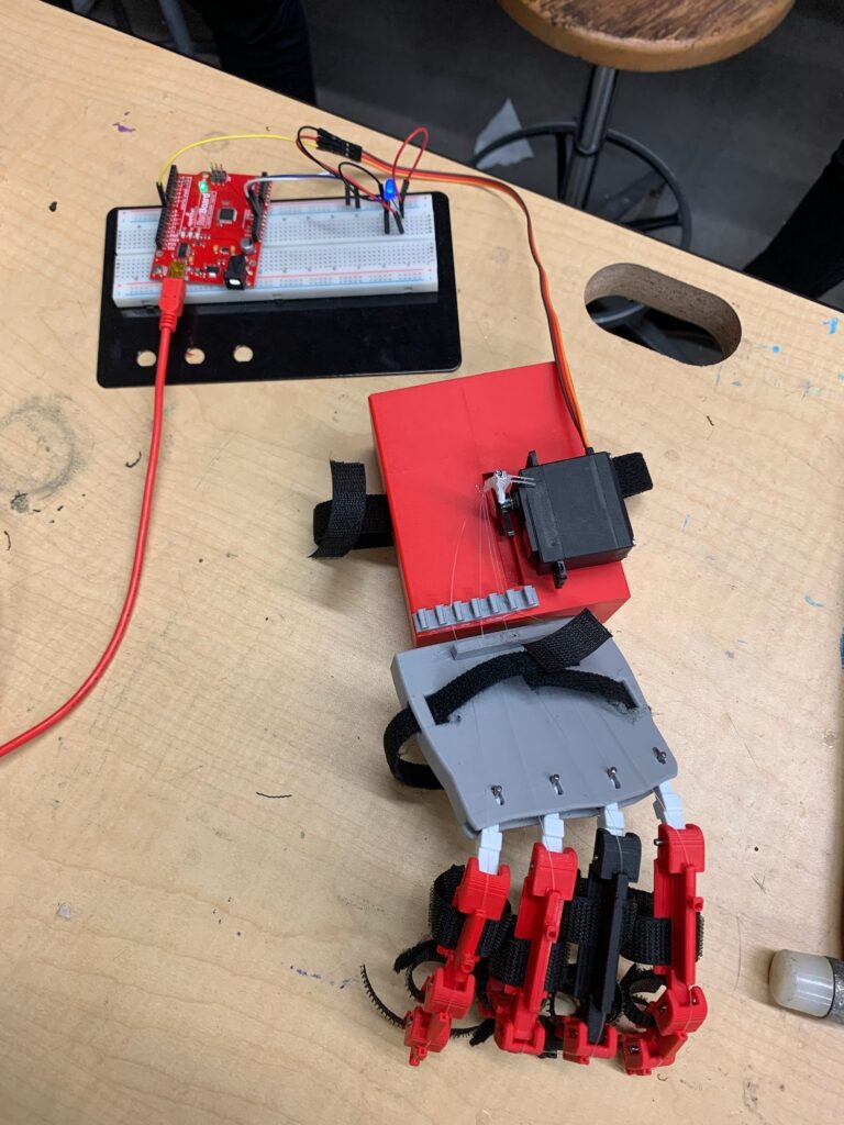
Design Concept III:
The primary aspect of this design concept is the accordion style hand cover. The new accordion style design allows the size of the back support to be adjustable to the size of the hand. The accordion design will also allow the back to be more flexible and change sizes with the movement of the fingers. Overall, this design is a fitted glove shape with necessary padding for comfort. The pieces are placed on top of each finger and secured in place with elastic bands instead of Velcro. The elasticity allows for a better fit of fingers of various circumferences without having to resize the bands every time. Wires attach the parts on the top of each finger and feed through holes in the accordion to reach back to the motor higher up on the arm. This concept will save time when putting the device on the patient and will be much more adjustable and comfortable.
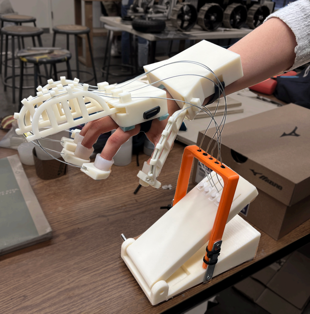
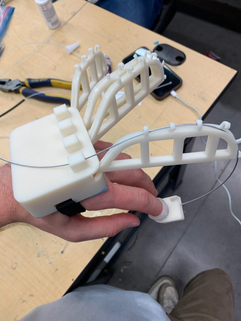
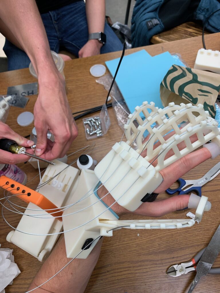
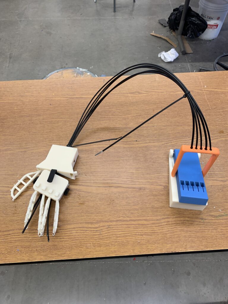
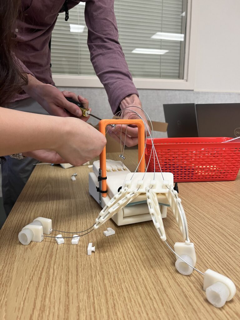
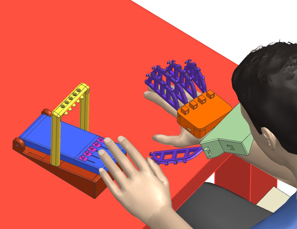
Final Design:
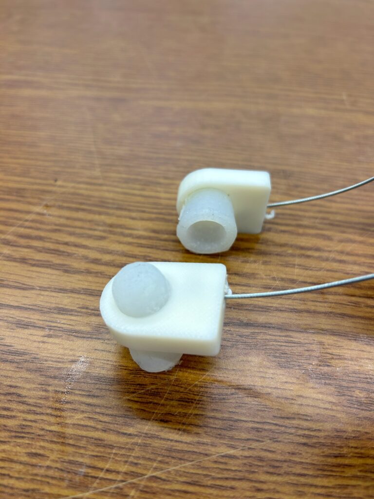
The final concept includes ABS finger rings with silicone finger attachments, a wrist attachment with foam padding and a Velcro strap, a hand attachment with foam padding and a Velcro strap, brake wires that attaches from the finger rings to the pedal, a foot/hand pedal, and TPU coverings to prevent the wire from releasing. Figure 4 shows the final design that was tested on patients at URMC rehab center. Appendix D shows a timeline of iterations for each part. The design was first fitted to an example hand that was scanned into NX and then adjusted to other hand sizes. Volunteers were collected, and a database was constructed consisting of lengths and circumferences of each finger, knuckle width, and wrist circumference. The averages were calculated and used to size the cantilever beams.
Finite Element Analysis:
Extensive finite element analysis(FEA) was performed to ensure that the chosen design would support the force applied by the patient while opening the hand without plastic deformation. For all tests a uniform material of ABS plastic was chosen within Nx for analysis.
Cantilever Beams
First, a single cantilever beam was analyzed for deformation and stress as shown in figures. The model was solved with linear statics with a 7lbf (31.15N) force applied on the inside edge of the far end of the cantilever and translationally fixed constraints of the other end. The results were as expected with a deformation less than 2cm at the very end and peak stress at the point where the bending starts.
Hand Assembly
Next, non-linear FEA was does on the entire hand assembly to get a better understanding of how the material will behave. Because the model is much bigger than the previous analysis, mesh controls had to be used in order to keep the detail of the mesh where needed and simplify the model everywhere else to made solving faster. Also, because the analysis consisted of five separate meshes, mesh mating conditions had to be applied to connect the meshes where the make contact. The results for the assembly analysis show an increase in deformation and a decrease in stress, this is likely due to the increased mesh size.
Pedal
Next, a simple FEA was performed on the part of the pedal where the cables attached to it. There were several assumptions made in the model to decrease unnecessary complexity in the model. The assumptions were as follows: the human input force is approximated as an evenly distributed force across the top of the far side of the pedal, the force from each of the cables were evenly distributed across the two faces on the underside of the cable cavity, the pedal was fixed on one end and not allowed to rotate to simulate worst case scenario, and all edge blends were removed. The mesh size for the analysis was the automatic element size of 13.6 mm, and the material is ABS. The human input force was approximated as 40 lbf or 178N. The force from the cables, or the total force to open all the fingers was 35 lbf divided by the 10 contact faces or 11.12 N each. The analysis showed both displacements and stresses that were well withing the tolerances of both the material and the assembly.