2008 News Archive
Enabling Low-Power Visual Sensor Networks
Professors in the Electrical and Computer Engineering Department of the University of Rochester have created wireless networks of low-power cameras that save vast amounts of energy. Their work is part of an NSF-sponsored $1.2 million project called "Being There" that is developing tiny, low-power, wireless video cameras that work together to produce high-quality video to provide the sense of "being there" for remote telepresence applications such as entertainment, education, and collaboration. Other potential applications of the team's discoveries include identification and tracking of military soldiers and equipment, livestock, and information-gathering robots on other planets; tracking the health of the disabled, ill, or elderly; and monitoring borders, machines, the activities of people, and places.
Mark Bocko, the Chair of Electrical and Computer Engineering, points out that together, the project covers the full spectrum of sensor network activity, "from the lowest physical level -- building sensors and then integrating signal processing into those sensors -- all the way up through the top-most level, which involves the protocols for creating self-adaptive networks out of the sensors." These networks can consist of tens to hundreds of video cameras, as well as devices that measure temperature, pressure, motion, sound, among many others.
The driving factor behind the research, says Bocko, is saving energy. Assistant Professor Zeljko Ignjatovic, the hardware expert on the team, explains that his video cameras are "about the size of a quarter" and consume "less than five percent" of the power needed by other video cameras. Depending on the applications using the mini-cameras, the research team expects to reduce overall network power consumption by 20-25%.
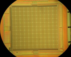
Quarter-sized mini video camera consumes less than 5% of the power needed by other video cameras and reduces overall network power consumption by 20-25%
Associate Professor Wendi Heinzelman, the architecture and protocol expert, along with her graduate student Stanislava Soro, have developed techniques to intelligently select which cameras send their data to meet the user's view requirements while extending the network operational lifetime. The idea is to determine which cameras are more critical based on their energy, position, and field of view, and to avoid using these critical cameras until necessary. This approach can considerably lengthen the time during which the network of cameras is capable of providing any view the user desires.
Associate Professor Gaurav Sharma, the imaging expert, works on algorithms that cobble together pieces of a scene from as many as a hundred tiny video cameras and makes sure the resulting video seen by users retains excellent resolution and quality. To accomplish this goal, his group also works on techniques for estimating the imaging geometry parameters for the multitude of cameras using only images captured by the system. The process, referred to as camera calibration, allows the "eyes" of the system to understand the parts of the scene they are viewing.
Camera Calibration for Low-Power Wireless Virtual Presence
The team's low-power, wireless image-based sensor networks provide a user with the sense that he or she is physically present in a remote location. The user can virtually move through the 3-dimensional space occupied by the sensor network and see images of the occupied space from any desired viewpoint. The system provides just enough data at the lowest acceptable temporal and spatial resolution and allows for varying requirements so the system can best use limited resources.
Calibration of the miniature video cameras is crucial to network operations. Reconstructing the user's desired view from several image parts requires knowledge of the set of cameras and the exact parts of the desired image that they provide. This necessitates that the system use highly precise camera calibration so it can determine the positions of the cameras relative to a reference coordinate system. Knowing the relative positions of the cameras allows the system to mosaic the image parts into a single reconstructed image. The quality of the mosaic image depends directly on the accuracy of the camera calibration.
Traditional camera calibration has relied on fixed camera settings that retain parameters such as focal length, principal point, and skew coefficients. The University of Rochester team has extended this traditional calibration by allowing for the most common situation where the camera zoom (and hence, focal length) changes. In this technique, a checkerboard pattern is used to calibrate different cameras. The calibration occurs based on the video received by each camera.
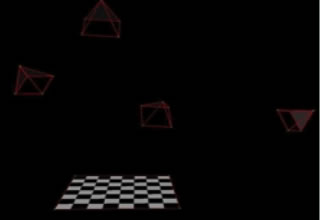
The checkerboard grid identifies the 3D location of each camera. The research team randomly puts cameras -- represented here by the four pyramids -- in a room using sticky tape. The location of each camera is pinpointed by its position relative to the checkerboard grid.
This calibration technique is extremely accurate and supplies improved mosaics of the images. The difference between the location of an actual camera and the camera calibration "estimate" is minimal, somewhere on the order of a 1% difference.
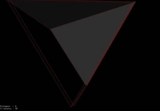
Difference between locations of calibrated camera "estimate" and actual camera: The topmost pyramid represents the actual camera location, while the bottom pyramid is the estimated camera location.
With the calibration done, the system partitions the entire space that contains all of the cameras. It identifies the three-dimensional cube in the space that each camera views. Based on this information, the system is able to select the correct set of cameras that supplies the user with what he wants to see.
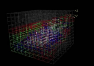
Each color shows how many cameras are viewing a particular 3D cube. If a cube is outlined in white, four cameras are focused on it. If outlined in blue, three cameras see it; if green, two cameras; and if red, only one camera is focused on the particular 3D cube. Where the 3D space is black, no cameras see that area.
Using this information, the system intelligently selects the cameras to use. If the system always chooses the cameras in the areas that are most viewed, more power is consumed and the cameras do not last as long. This means that the system could lose viewing coverage over time.
To conserve energy and keep the cameras active for longer periods of time, the system turns the cameras on and off based on the desired view at any particular time. If an entire view is covered by lots of cameras and one camera dies, then it is not a big deal: the user can see any view simply by using other cameras. However, if there is only one camera covering a particular area (say, the areas outlined in red in the above image) and this camera dies, then it is a big deal. The system uses these critical cameras only when needed. If any other camera can be used to view a white area, for example, then that camera is used instead. This supplies better camera coverage over time.
The trade-off is that a "critical" camera may actually provide a higher quality image to the user, based on the user's desired view. Quality of the image is measured in terms of PSNR (Peak Signal-to-Noise Ratio). Thus, the user can tune a knob to specify whether higher quality images is more important or longer network lifetime is more important, and the sensor selection algorithm can appropriately select the cameras to meet the request.
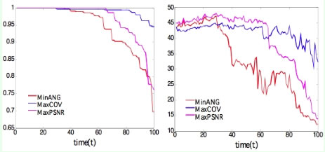
The blue line shows coverage (left) and the PSNR (right) over time for the intelligent camera selection algorithm that avoids "critical" sensors. 95% coverage of the room is achieved for 50% longer using this approach than a standard approach (red line), with an initial drop in PSNR of less than 3 dB. The purple line shows a selection algorithm that selects the camera to provide the "best" reconstructed image—this approach is not possible in practice.
-lhg
